I wanted to build a fully remotable LZ1AQ Active Antenna controller with off the shelf components. It is very cheap to buy ESP8266 MCUs and multi-channel relay boards online. Why reinvent the wheel? This project can be easily adapted to control remote antenna switches and other devices that can be controlled with relays.

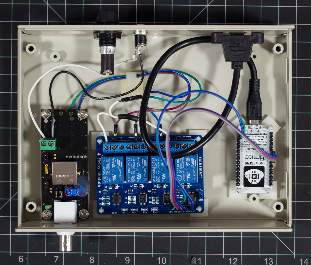
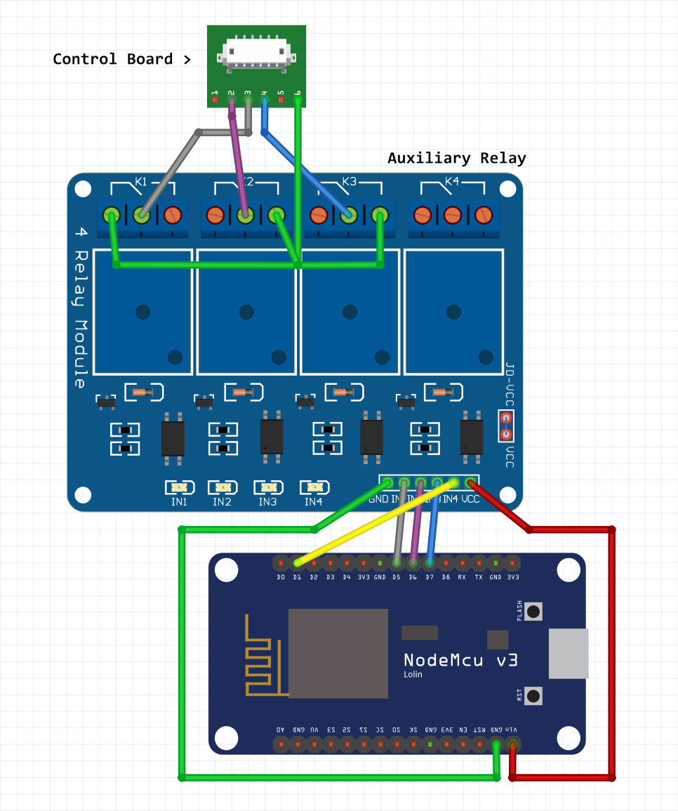
Wiring Diagram
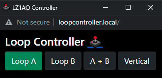
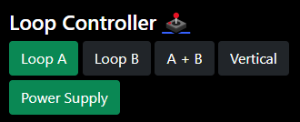
Usage
Navigate to http://loopcontroller.local/
Auxiliary Relay
Relay 4 connects to pin D1 (GPIO 5)
You can enable the 4th relay by setting bool auxEnable = true;
You can invert the button color for normally closed by setting bool auxNC = true;
You can set the button label by changing const char *auxLabel = "Relay 4";
I have mine set to power off the loop remotely wired in the normally closed position.
For additional relays I suggest using a project like Tasmota.
Bill of Materials
| Part Number | Description | QTY |
|---|---|---|
| NodeMCU V2 | Microcontroller with ESP8266 | 1 |
| N/A | 4 Channel Relay Module (Active Low) | 1 |
| RM2055M | Hammond Enclosure (50 mm x 140 mm x 190 mm) | 1 |
| HC-6 | Adhesive PCB Supports | 8 |
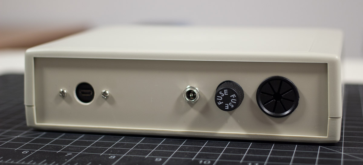
| BK/HTB-24M-R | Fuse Holder 5mm x 20mm | 1 |
| 5MF 300-R | Fuse 300 mA 5mm x 20mm | 10 |
| N/A | DC Connector of your choice | 1 |
| N/A | Panel Mount Micro USB Extension | 1 |
| PGSD-8 | Cable Grommet | 1 |
| N/A | Hookup Wire | Lots |
| N/A | Dupont Jumpers Wires | Lots |
I used PC Motherboard standoffs and screws to rest the power inserter in the enclosure. It is not mounted permanently to allow easy removal of the front panel.
LZ1AQ Documentation
1 0 0 Loop A
0 1 0 Loop B
1 1 0 A + B
0 0 1 Vertical
Note: My code has pin 1 inverted so Loop A is in the Normally Closed position. This allows the loop to function in A mode with no power applied to the MCU or relay board.

LZ1AQ FAQ: Can the antenna switching be performed digitally?